Ford Viscosity Cups
Article No. 13617
Ford Standard Cup #1 with Stand
- Standard Ford Cup #1
- Bracket Stand
- Glass Plate with Level
- Beaker NOT included
Download Excel Viscosity Chart HERE
Certificate:
Features
Ford Standard Ford Cups
- Orifice sizes: No. 0, 1, 2, 3, 4, 5
- The flow formula for each cup in the series has been selected to provide results, which are as close as possible to an average of other similar Ford Cups. The flow formula as applied to the physical dimensions of each cup in the series has been confirmed with the use of standard oils traceable to the National Institute of Standards and Technology and other liquids from essentially zero viscosity to a viscosity proportional to 150 seconds flow time.
- The top interior of the orifice has been shaped to provide a sharper break in the stream as the cup empties. The design also provides for a better definable orifice length with respect to theory.
- The taper fit of the orifice eliminates hard to clean areas.
- The orifice is readily removable with furnished wood dowel and inserted without the use of tools.
- The design of the cup bottom gives increased protection to orifice.
- The drip ring has been deepened to accommodate a greater amount of material
- ± 2% Production Tolerance
- Cup No. 5 compatible to requirements of federal specification MMM-A-121 for adhesives
- Qualify under MIL STD 45662A & conform to ISO 9000 when ordered with calibration certification.
- A specially designed tripod support is available to enhance the use of the cup.
- Weight of the cup has been reduced 20% to minimize influence of cup temp on the temp of the material being measured.
Technical Attributes
-
- Cup Model
- Ford Standard Cup with Stand & Cover
-
- Cup No.
- 1
-
- Data
-
Ford Standard Cups Ford Standard Cup Number Conversion Chart
Seconds RangeConversion Chart
Centistoke Viscosity RangeCalibration Liquid 0 57 to 120 2 to 14 G-6 1 60 to 120 12 to 40 G-10 2 37 to 120 25 to 120 G-35 3 23 to 120 29 to 273 G-60 4 16 to 120 34 to 441 G-60 5 10 to 120 77 to 1413 G-200
More Information
Ford Standard Cup
The internal dimensions conform to those specified in the ASTM Method D1200 except for the diameter of the orifice. Even here there is close agreement, but the diameter of the orifice is adjusted to bring the cup into conformity with the flow formula. Most of the Ford cups produced by others to date have an external cup diameter that extends below the level of the orifice. This results in a large amount of metal adjacent to the orifice which can adversely affect the accuracy of the reading if the cup and material being measured are not at the same temperature at the time the measurement is started. Most of this mass of metal has been removed in the new design. The bottom of the cup is designed to extend below the orifice. This design not only provides adequate stability for the cup when resting upright on a surface, but it also protects the orifice from damage. This protection is also closer to the orifice than in other designs.

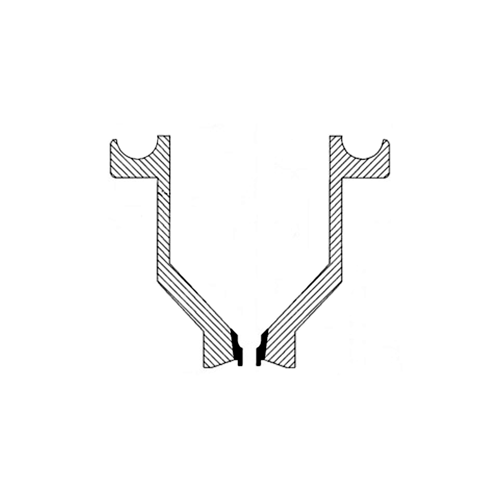
The drip ring surrounding the top of the cup has been increased in volume to accommodate a greater amount of material. This change minimizes the frequency of cleaning or reduce spillage in long series of tests. Pictured on the right is a cross section of the orifice used in both the Gardco Standard and the Gardco Ford Dip Cups. Note that the upper interior portion, following the conversion from the slope of the cup interior is spherical in shape rather than conical. It has been found that this shape provides a cleaner break of the stream as the cup empties. In addition, the length of the orifice is better defined in accordance with theory. The "0" orifice does not have this feature as it is longer and has less need of this shape. In the new design the exterior of the brass orifice is a truncated cone, sized to match a conical section in the body of the cup. This design insures close fit with no gaps between the body and the orifice either at the top or bottom. This design also eliminates the hard to clean areas that exist in most other designs.

Orifice Removal: To remove the orifice, simply place the cup upside down on a solid surface, place a wood dowel rod (VI-WD) against the orifice and tap the dowel rod with an object such as a paperweight. To insert the orifice, place the cup on a solid surface right side up, drop the orifice in place, place the dowel rod into the spherical section of the orifice and tap the dowel rod with a heavy object.
Click HERE for more information on Viscosity Cups.
Standards
- ASTM D333
- ASTM D365
- ASTM D1200
Procedure
It is helpful, and results will be more consistent, if all viscosity determinations are made in a room that is free from drafts or quick temperature change, and is within ±3°C (±5°F) of the viscosity measuring temperature of 25°C.
Ford Standard Cup
- Adjust the sample to measuring temperature, usually 25°C (77°F).
- Select the cup that will provide readings which are well within the cup range.
- Make sure that the cup is clean and place it into its support.
- Make sure that the cup is level.
- Place a finger under the cup orifice and fill the cup with bubble free test material. The cup is full when the meniscus disappears where the liquid joins the sidewall of the cup. If the cup is overfilled, scrape the access into the cup well with a spatula or by passing the cover plate across the top of the cup. Note that the finger can be removed from the orifice when the cover plate is in place.
- Start a timer as the cover plate is removed from the cup.
- Determine the temperature of the efflux stream. If there is a significant change during the test it should be repeated.
- Stop the timer at the first break of the efflux stream, one or two inches below the orifice.
- Record the cup type and number, measured temperature, and efflux time. For best accuracy, average three or more readings.
- Promptly clean the cup, giving special care to the orifice.
Delivery Content
Standard Ford#1 Cup, Bracket Stand, Glass Plate with Level
Knowledge
Want to learn the perfect process for using a viscosity cup? The article link below provides information on how to choose the right viscosity cup, how to measure efflux time, how to remove calibration oils and much more. - The Proper Process for Measuring with a Viscosity Cup
Accessories
Other Variations


